PROTOTYPE BOARD CONSTRUCTION AND USE
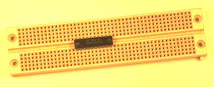
The Prototype Board is designed to allow electronic circuits to be connected together quickly, without soldering, to investigate their performance. The holes, in the plastic top surface of the board, have their centres spaced one tenth of an inch apart to match normal component dimensions. The picture shows a simple board with an Integrated Circuit, or IC, placed on it. Note that the gap between the two sections is also a multiple of tenths of an inch to enable the connections of the chip to fit in both X and Y directions.

The connections on the board are made by brass contact strips connecting a number of holes together in groups. The connection, from the component, is pushed through a hole in the top of the prototype board to connect with the brass contact strip underneath. The simple board, illustrated at the top of the page, has each group of five holes connected together. The diagram illustrates a more common type of board, which has an additional strip of holes running along each edge of the board. This strip is useful for any connections which are required at several different parts of the board, such as a power supply or the common zero volt line, as all the holes are connected together. The connections formed by the brass contact strips are shown in red below for a typical prototype board.

Pieces of solid insulated wire, with 5mm of insulation removed at each end, are used where the brass contact strips have to be inter-connected to complete a circuit.